01 / TEXTILE
Cam Component
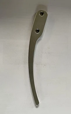
Cam components for texturing machinery, identified by profile, hole positions and mounting relationships. Provide the machine model, part number and profile dimensions.
View details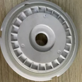 COMPONENT PHOTOGRAPH
COMPONENTS / TEXTILE
Cams, spacers, springs, support plates, pins and clamping disks for equipment manufacturing, maintenance and spare-parts sourcing.
Material, dimensions and performance follow the confirmed drawing, sample and acceptance conditions.
COMPONENT / APPLICATION
Texturing machine and textile machinery components. Establish fit using the machine model, part number, installation position, photos or samples, then confirm dimensions, material, quantity and delivery requirements.
EXPLORE THE FAMILY
Select a component to review material, geometry and selection details.
Cam components for texturing machinery, identified by profile, hole positions and mounting relationships. Provide the machine model, part number and profile dimensions.
View details
A spacer sleeve for equipment assembly and mating positions. Key selection details include bore, outside diameter, length, end faces and mating dimensions.
View details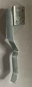
A bent spring for textile machinery. Discuss fit using installation direction, bend geometry, connection positions and material requirements.
View details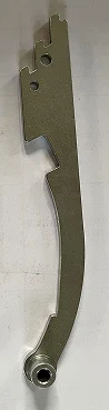
A spring hanger for texturing machinery. Check connection holes, formed profile and installation direction, including its relationship with adjacent components.
View details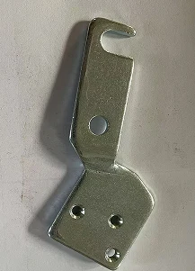
A support plate for textile equipment. Confirm a drawing or sample covering mounting holes, plate thickness, support surfaces and outer profile.
View details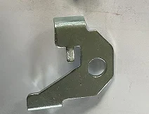
A left brake plate for a texturing machine. Check the machine model, left/right orientation, holes, profile and mating dimensions with neighboring components.
View details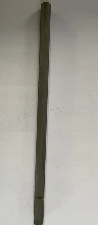
A pin for textile machinery. Review diameter, working length, end geometry, material and mating relationships, then confirm supply against the drawing.
View detailsA clamping disk for texturing machinery. Check diameter, center bore, face geometry and mounting arrangement using the machine model and a sample.
View detailsTECHNICAL BRIEF
A clear brief helps define selection, sampling and the manufacturing approach.
Machine model, part number and installation position
Front, side, hole and connection-point photos
Critical dimensions, material, left/right orientation and mating fit
Quantity, spare-parts plan and delivery requirements
HOW WE WORK
Machine model, part number and position
Photos, samples and critical dimensions
Material, quantity and fit requirements
Inspection, packaging and delivery
LET’S MAKE IT PRECISE
Material · Dimensions · Quantity · Critical requirements · Application